
Bulk storage
Hopper volume, bed depth, loading height, level sensing and refill method are chosen around component behaviour and required autonomy.
Industrial step feeder systems
From low-level bulk storage to controlled single-part release, each mechanism, sensor and interface is defined around production samples and the downstream process.
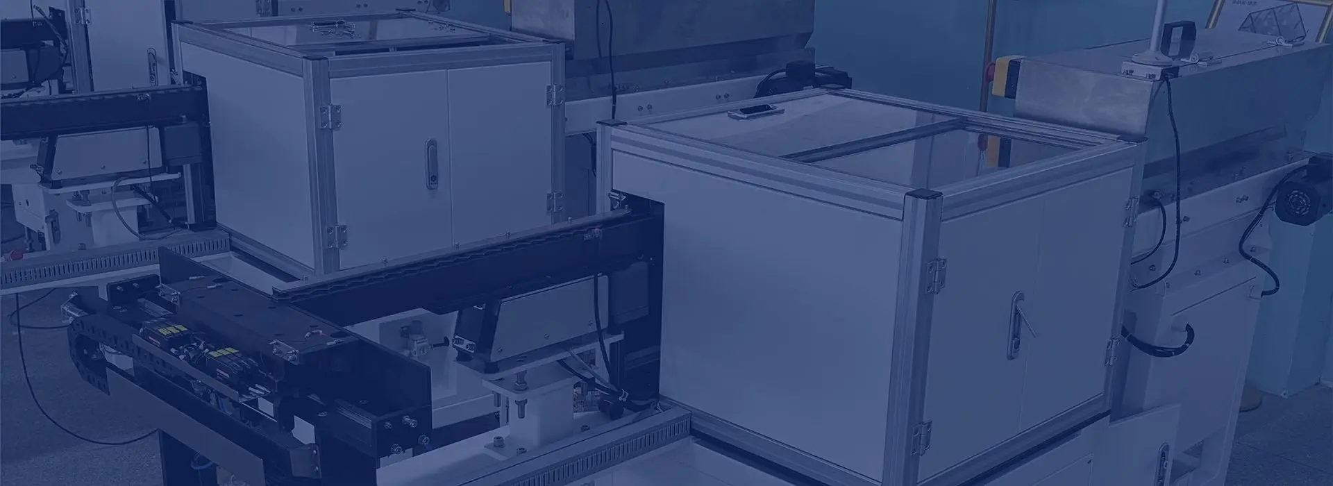
The lifting section meters and elevates parts; track tooling completes orientation and presentation.
Operating principle
Reciprocating plates rise through the component bed. Each stroke carries a controlled layer upward, while gravity and geometry allow unsuitable presentations to return to the hopper.
Correctly settled parts transfer to a rail or linear track. The track can then accumulate, inspect and orient the component before an escapement creates the final machine interface.
System architecture
A well-specified step feeder separates each function clearly, then controls them as one system.
Hopper volume, bed depth, loading height, level sensing and refill method are chosen around component behaviour and required autonomy.
Step geometry, stroke, cycle speed and drive are selected to elevate the useful layer without excessive product impact.
The transition from the upper step to the track is engineered to prevent bridging, rollback, overlap or uncontrolled drop.
Guides, rails, gravity features, mechanical tooling, sensors or vision establish the accepted datum.
A linear buffer decouples feeder motion from downstream demand and provides track-full feedback.
One part is isolated at the agreed pitch and position for pick-up, insertion, assembly or transfer.

Bulk storage, feed path and downstream transfer can be supplied as one coordinated system.
Configuration options
The final scope can include the mechanical platform, controls and line interfaces needed for safe, repeatable operation.
Specification data
Drawings are useful, but physical samples reveal friction, bounce, nesting, contamination, mould variation and other real-world behaviour.
Straight answers
The feasible range is application-specific. Step feeders are commonly evaluated for bolts, pins, shafts, clips, mouldings, closures and other parts that benefit from low-level loading and controlled elevation.
Most systems use a track or rail after the lifting section to complete orientation, provide accumulation and create a stable interface with the escapement or receiving machine.
Yes. Hopper capacity, loading height and refill method can be engineered around batch size, operator access, component weight and the line's autonomy target.
Sensors monitor the output track and stop or start the lifting cycle as demand changes. The useful figure is sustained accepted output at the agreed hand-off, not the number of parts moved within the hopper.
Application review
Send a drawing or photograph, the component range, required orientation, sustained output and receiving-machine details. We will identify the most suitable next step.
Step feeder knowledge centre
Compare principles, define the application and arrive at a quotation or trial with the evidence needed for a useful answer.
Compare feeding principles by component, noise, rate and hand-off.
Read the guide →Engineering guidance for bolts, screws, pins, nuts, bushes and shafts.
Read the guide →Understand lower-vibration bulk feeding and realistic noise objectives.
Read the guide →Build a complete brief from components, rate, layout and acceptance evidence.
Read the guide →See which tooling, controls, guarding and integration choices determine scope.
Read the guide →Define the verified datum, buffer and one-part machine release.
Read the guide →Protect feed-path geometry, sensing, alignment and fault recovery.
Read the guide →Get direct answers to common engineering and purchasing questions.
Read the guide →